Espruino is a board that comes with a pre-installed firmware capable of running JavaScript code. You can buy one of the official board or you can flash a list of “not officially supported” boards. The list contains also the ESP8266 board, so let’s try to run our JavaScript code on it.
For this article I’m using a NodeMCU Amica board which lets us play with the ESP8266 (ESP-12) without the burden of connecting it to the computer and also powering it to the right voltage all from a micro USB port.
All the programs in the article are run from a Linux Mint 17 operative system.
Flash the firmware on ESP8266
First step is to flash the Espruino firmware into the ESP board. You can find a tutorial in the Espruino site. In this article I’m putting a short list of instructions ready to use.
Create a working folder and download there the ESP tools.
mkdir espruino
cd espruino
wget https://github.com/themadinventor/esptool/archive/master.zip
unzip master.zip
The ESP tools are a set of Python scripts necessary to flash a firmware in the ESP board.
We need now a ESP8266 dedicate version of the Espruino firmware. You can find the latest version in this forum post. Here the instructions to download the last version available today (26/06/2016):
wget http://s3.voneicken.com/espruino/espruino_1v85.tve_master_124390c_esp8266.tgz
tar -xvf espruino_1v85.tve_master_124390c_esp8266.tgz
We are ready to flash our board. The following instruction are for a ESP-12 board connected to the /dev/ttyUSB0 port. Please refer to the original tutorial for a different version of the ESP board.
cd espruino_1v85.tve_master_124390c_esp8266
../esptool-master/esptool.py --port /dev/ttyUSB0 --baud 115200 \
  write_flash --flash_freq 80m --flash_mode qio --flash_size 32m \
  0x0000 "boot_v1.5.bin" 0x1000 espruino_esp8266_user1.bin \
  0x3FC000 esp_init_data_default.bin 0x3FE000 blank.bin
The blue led in the board will start blinking and you will see the following output in console:
esptool.py v1.2-dev
Connecting...
Running Cesanta flasher stub...
Flash params set to 0x004f
Writing 4096 @ 0x0... 4096 (100 %)
Wrote 4096 bytes at 0x0 in 0.4 seconds (90.2 kbit/s)...
Writing 462848 @ 0x1000... 462848 (100 %)
Wrote 462848 bytes at 0x1000 in 40.1 seconds (92.4 kbit/s)...
Writing 4096 @ 0x3fc000... 4096 (100 %)
Wrote 4096 bytes at 0x3fc000 in 0.4 seconds (90.2 kbit/s)...
Writing 4096 @ 0x3fe000... 4096 (100 %)
Wrote 4096 bytes at 0x3fe000 in 0.4 seconds (90.5 kbit/s)...
Leaving...
(Did you noticed the “Running Cesanta flasher stub…” print? Looks familiar?)
If you’re having problems finding the correct device path in Linux:
- first check that you’re using an USB data cable. The first time I’ve tried I was getting crazy because I was using a simple power USB cable.
- second try this console command to print the system events when the USB cable is plugged:When you plug the cable you will get something like this:
watch -n 0.1 "dmesg | tail -n $((LINES-6))"[ 5597.132098] usb 6-1: new full-speed USB device number 11 using uhci_hcd [ 5597.298148] usb 6-1: New USB device found, idVendor=10c4, idProduct=ea60 [ 5597.298156] usb 6-1: New USB device strings: Mfr=1, Product=2, SerialNumber=3 [ 5597.298160] usb 6-1: Product: CP2102 USB to UART Bridge Controller [ 5597.298163] usb 6-1: Manufacturer: Silicon Labs [ 5597.298165] usb 6-1: SerialNumber: 0001 [ 5597.304121] cp210x 6-1:1.0: cp210x converter detected [ 5597.306173] usb 6-1: cp210x converter now attached to ttyUSB0
After the flash operation the board is ready to receive your JavaScript commands!
To send the commands you need to connect to the board using a serial connection (through the USB port). Under linux you can use the screen program:
screen /dev/ttyUSB0 115200
Now you can send JavaScript commands that will be interpreted and the output provided as response.
For example writing:
1+1
you will get:
=2
You can call functions, for example:
reset();
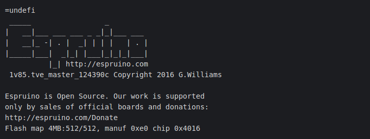
it will reset the board and print a boot message:
=undefi
 _____                 _
|   __|___ ___ ___ _ _|_|___ ___
|   __|_ -| . |  _| | | |   | . |
|_____|___|  _|_| |___|_|_|_|___|
          |_| http://espruino.com
 1v85.tve_master_124390c Copyright 2016 G.Williams

Espruino is Open Source. Our work is supported
only by sales of official boards and donations:
http://espruino.com/Donate
Flash map 4MB:512/512, manuf 0xe0 chip 0x4016
Time to use the Espruino Web IDE.
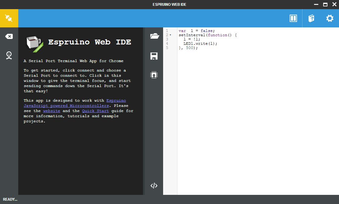
Espruino Web IDE
The Espruino project provides a Web IDE for editing and uploading your JavaScript code to your board. The IDE also manages the modules that can be used in your code in order to extend the basic functionalities offered by the SDK, for example to use the Wi-Fi device or external sensors like the DHT-22.
The Web IDE can be installed as Chrome application or as NodeJS package.
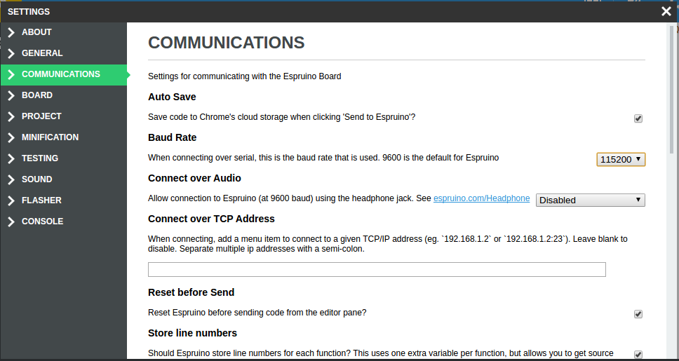
After the IDE has been installed we have to configure the baud rate in order to have the communication with the board working fine. Click on the gear icon on the top right, select the COMMUNICATIONS tab, then set the “Baud Rate” to 115200.
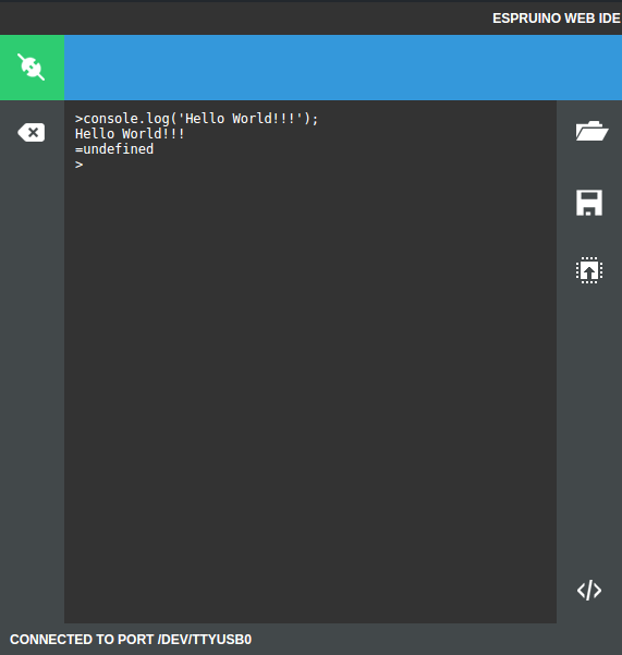
Now everything is ready to play. Click the connect button on the top left, select the USB port to use and the IDE will connect to the board.
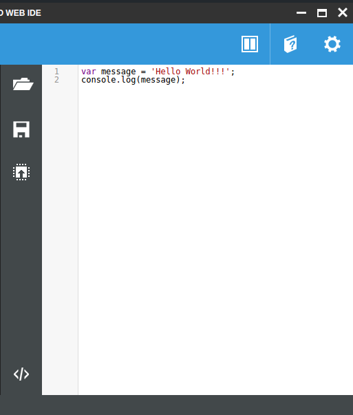
On the left side you can write commands directly to the board and get the response live.
On the right side you can write your code and then upload it to the board using the upload button on the center.
Now we ready to write our first JavaScript program to run on our ESP8266 board!