As free time project I’ve built a digital clock using Arduino Duemilanove, the DS1307 Real Time Clock, the MCP23017 port expander and a bunch of blue leds.
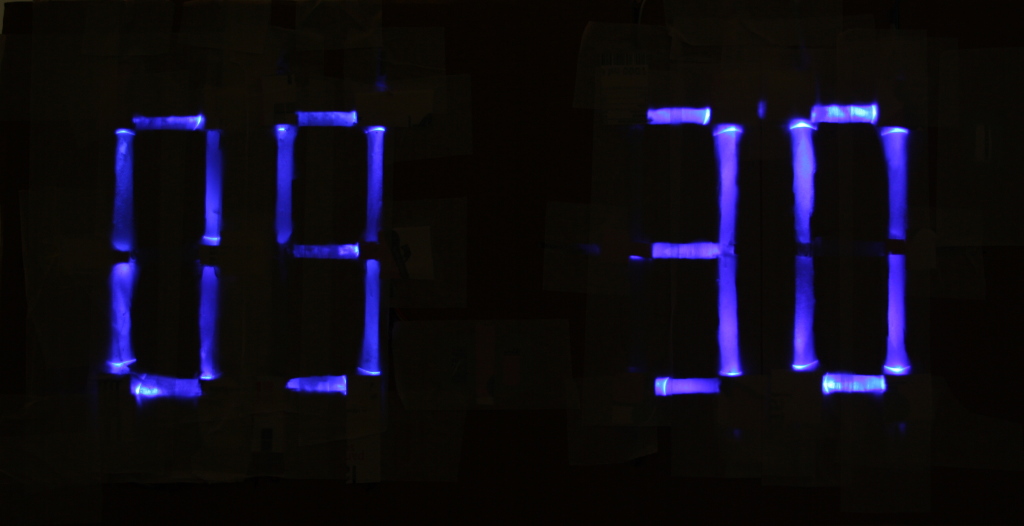
Seven segment display
The idea is to show the current time using four 7 segment display, the display are built using some leds and a cardboard.
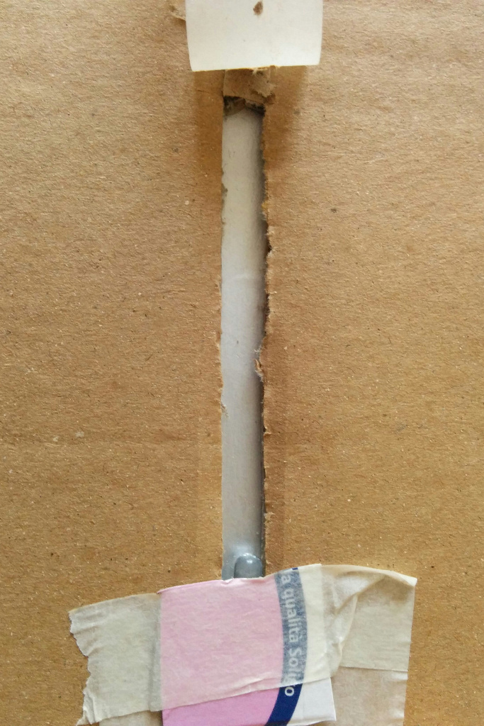
Each digit segment is realized using a blue led. The led is inserted in a hole partially covered with reflective material (I’ve used the internal part of a Tetra Pack container). The front part is covered with masking tape.
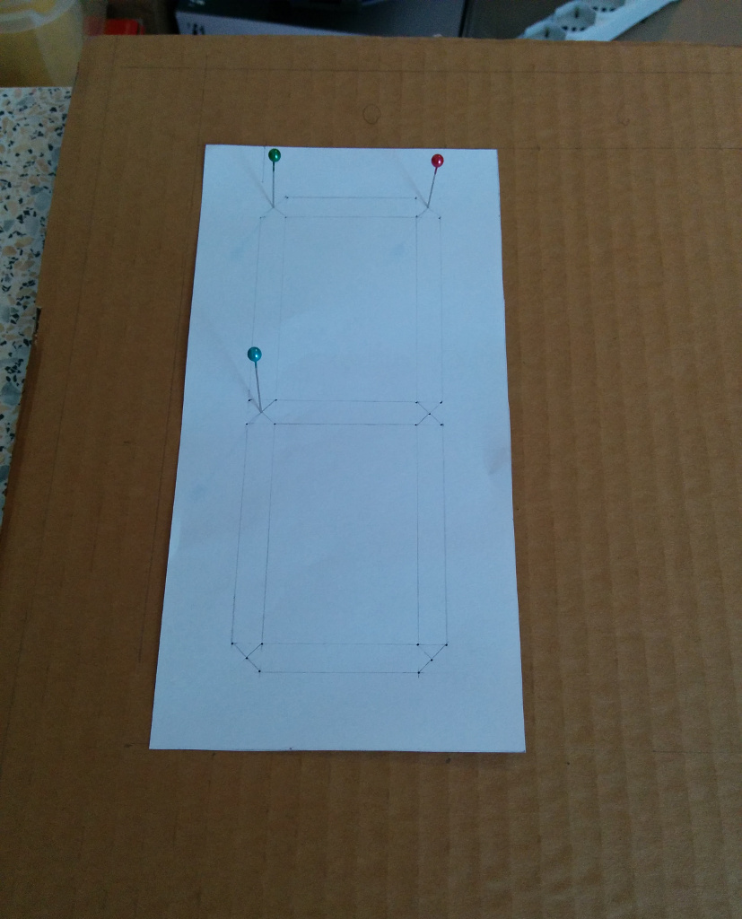
Each digit has seven segments. The segments holes have been made in a cardboard using a stencil.
Controlling the seven segment display
The first two digits segments are controlled by the MCP23017 port expander, the other two are controlled directly using the Arduino ports.
The MCP23017 port expander can control 16 ports, the 16 ports are managed by two registry. The port expander is controlled by Arduino using I2C.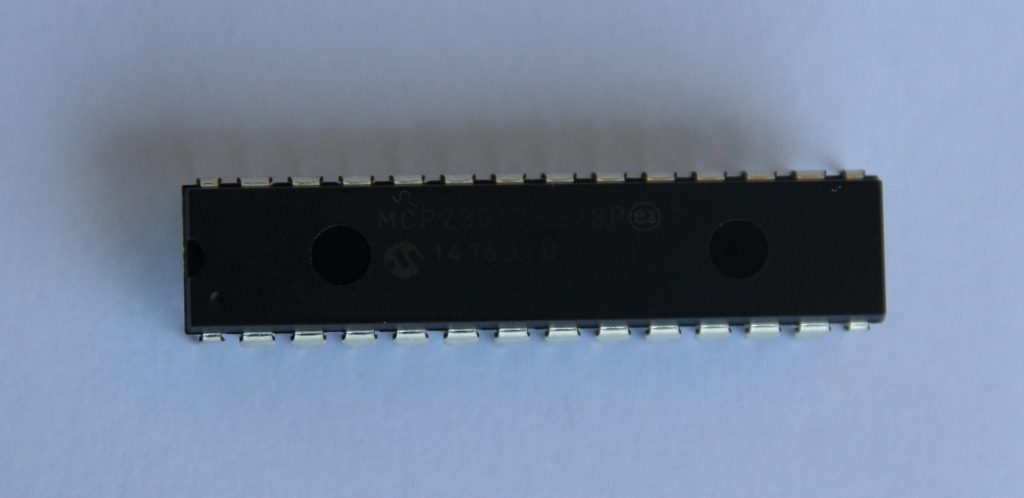
The single registry controls 8 ports and you can set which ports are ON or OFF using a byte. Each bit of the byte tells the port expander if the port should be ON or OFF.
For example in the following image you can see the registry turning ON leds 1 and 4 having his value set to 9.
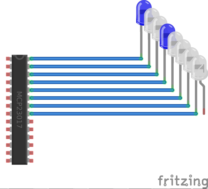
Here you can see the bits converted to the byte value 9:
port 1   2   3   4   5   6   7   8
bits 1   0   0   1   0   0   0   0
     1   2   4   8  16  32  64 128
     1           8                 = 9
I’ve used one registry for digit then I’ve left unused one port for registry.
In order to identify each segment they have been labeled as follow:
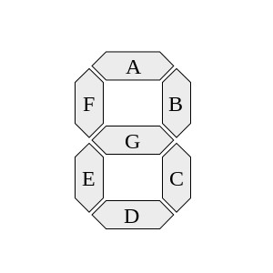
Assigning each port to a single digit segment you have this mapping:
   A   B   C   D   E   F   G
   1   2   3   4   5   6   7
   1   2   4   8  16  32  64
For example if you want to display the digit 2 you need to turn ON segments A, B, G, E and D.
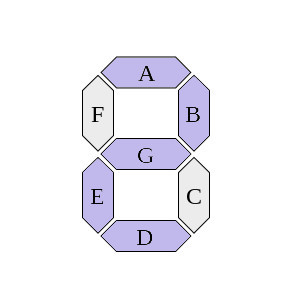
In order to do so you have to set the registry value to 91 (0x5B in HEX).
   A   B   C   D   E   F   G
   1   2   4   8  16  32  64
   1   1   0   1   1   0   1
   1   2       8  16      64 = 91 (0x5B)
I wasn’t lucky and due to wires length and leds positions I had to connect the leds to the ports in a random order getting such mapping:
   E   D   G   C   A   F   B
   1   2   4   8  16  32  64
   1   1   1   0   1   0   1
   1   2   4      16      64 = 87
This random order required to “re-map” the segments before converting it as byte.
Here you can find a nice tutorial about the MCP23017 port expander.
The remaining two digit segments are controlled one by one using Arduino ports and standard digital write.
The time
The time is keep using the DS1307 RTC. The RTC is controlled through I2C and the RTC library.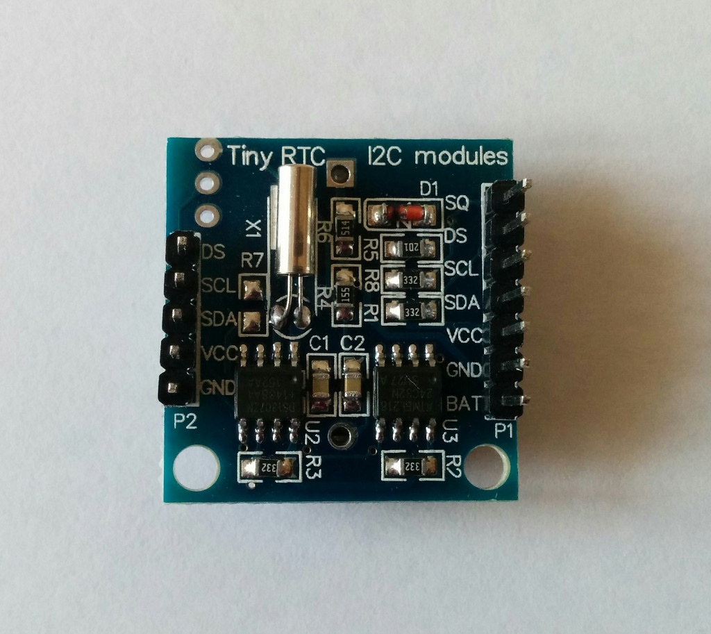
Schema
Here a schema of main components connections.

The code
#include <Wire.h>
#include "RTClib.h"

//Real time clock
RTC_DS1307 rtc;

// Digit segments labels:
//
//     a
//    ---
// f |   | b
//    --- g
// e |   | c
//    ---
//     d
//

// mapping between segments and registry for digits managed by MCP23017 port expander
                   // a   b   c   d   e   f   g
int segmentsA[7] = { 16, 64,  8,  2,  1, 32,  4};
int segmentsB[7] = {  1,  4, 16, 32, 64,  2,  8};

// mapping between arduino ports and segments for digits managed directly by Arduino
                   // a   b   c   d   e   f   g
int segmentsC[7] = {  2,  0, 10, 13,  9,  4,  8};
int segmentsD[7] = {  5,  7,  6, 12, 11,  1,  3};

// mapping between digits and segments bits configuration
byte digits[10] = {0x3F, 0x06, 0x5B, 0x4F, 0x66, 0x6D, 0x7D, 0x07, 0x7F, 0x6F};

void setup() {

  //i2c setup
  Wire.begin();

  //setup MCP23017 registries
  Wire.beginTransmission(0x20);
  Wire.write(0x00); // IODIRA register
  Wire.write(0x00); // set all of port A to outputs
  Wire.endTransmission();
  Wire.beginTransmission(0x20);
  Wire.write(0x01); // IODIRB register
  Wire.write(0x00); // set all of port B to outputs
  Wire.endTransmission();

  //setup arduino ports
  for (int i = 0; i< 14; i++) pinMode(i, OUTPUT);

  //RTC setup
  rtc.begin();

  if (! rtc.isrunning()) {
    // following line sets the RTC to the date & time this sketch was compiled
    rtc.adjust(DateTime(F(__DATE__), F(__TIME__)));
  }

  //clear clock digits
  clearClock();
}

void loop() {

  //get time from RTC
  DateTime now = rtc.now();

  //prints hour and minutes
  print(now.hour(), now.minute());

  delay(500);
}

//prints hour and minute
void print(int hour, int min) {
  printHour(hour);
  printMinute(min);
}

//prints hour digits
void printHour(int hour) {

  //extract the two digits from the hour value
  int h = hour%100;
  int hd1 = h%10;
  int hd2 = (h/10)%10;

  int d1 = mapSegments(segmentsA, hd1);
  int d2 = mapSegments(segmentsB, hd2);

  writeARegistry(d1);
  writeBRegistry(d2);
}

//prints the minute digits
void printMinute(int min) {

  //extract the two digits from the minute value
  int m = min%100;
  int d1 = m%10;
  int d2 = (m/10)%10;

  printDigit(segmentsC, d2);
  printDigit(segmentsD, d1);
}

//clear the clock digits
void clearClock() {

  writeARegistry(0);
  writeBRegistry(0);

  clearDigit(segmentsC);
  clearDigit(segmentsD);
}


/** HELPERS **/

//writes into the A registry of MCP23017
void writeARegistry(int value) {
  Wire.beginTransmission(0x20);
  Wire.write(0x12); // GPIOA
  Wire.write(value); // port A
  Wire.endTransmission();
}

//writes into the B registry of MCP23017
void writeBRegistry(int value) {
  Wire.beginTransmission(0x20);
  Wire.write(0x13); // GPIOB
  Wire.write(value); // port B
  Wire.endTransmission();
}

//translate the digit into a registry bits configuration
byte mapSegments(int segments[], int digit) {

  //the segments configuration
  byte bits = digits[digit];
  int pow = 1;

  //registry configuration
  int registryBits = 0;
  for (int i = 0; i< 7; i++) {
    registryBits += (pow & bits)?segments[i]:0;
    pow = pow*2;
  }
  return registryBits;
}

//turn on the segments for the specified digit
void printDigit(int segments[], int digit) {

  //segments configuration
  byte bits = digits[digit];

  int pow = 1;
  for (int i = 0; i< 7; i++) {
    //turns on the segment based on digit configuration
    digitalWrite(segments[i], pow & bits?HIGH:LOW);
    pow = pow*2;
  }
}

//turn off all the specified segments
void clearDigit(int segments[]) {
  for (int i = 0; i< 7; i++) digitalWrite(segments[i], LOW);
}

//turn on all the specified segments
void all(int segments[]) {
  for (int i = 0; i< 7; i++) digitalWrite(segments[i], HIGH);
}
In the setup phase the program setup the I2C library, the RTC library and the Arduino ports.
In the loop phase it reads the current time value from the RTC and “print” it.
The hour value is split into two digits, each digit is mapped into a segments configuration then translated in a byte value for the registry. Finally the byte value is sent to the correct registry.
The minute value is split also into two digits, each digit mapped into a segments configuration and then each Arduino port set consequently.